Friday, July 5, 2013

Small Build, Big Execuition

GOOD PRACTICES

Sometimes its not the complexity of a project that makes it noteworthy, its the way in which it was built. A prime example of this is in a recent project of mine where I was asked by a coworker to build a small and simple device to act as a monetary off switch. It uses a 555 timer to give a momentary pulse to a relay that switches a high power load off for a fraction of a second. Because of the simplicity of this project it will be easy to see the good practices I used to make the device more reliable, easier to repair, modify and operate.

OUTSIDE IN

A rats nest of wires on a breadboard is not a finished project, it is an easily damaged mess. Things need to be permanently soldered together, glued to keep them from bending or breaking and protected by an enclosure. The enclosure has always been the hardest part for me so I like to start with it. I selected a small project box from radio shack (I keep some on hand) and designed everything to fit in it.

Source: beavishifi.com

NOT A BUILD LOG

I didn't take photos during the build of this project so I will show the photos of the finished item and tell you the good practices used.

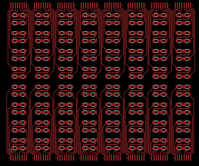
Instructions for use and schematics for all boards

Turn pot accessible from outside. This allows adjustments to timing without dissembling the unit. It was recessed and designed to be only adjustable using a screwdriver so accidental changes were unlikely.

Proper use of space. Many different configurations were test fitted to determine what looked and worked best.

The battery is easy to remove without disrupting the other parts.

The 555 timer board has sockets and connectors to allow it to be removed without de-soldering or cutting anything. The board was also cut to size so it would fit nicely in the cases's vertical PCB slots.

The main IC (555 timer) is in a socket to it can be removed and replaced without de-soldering. The turn pot is hot glued down so the legs are not bearing the load

All wires are hot glued for strain relief.

The relay board uses header pins so it can be easily removed and replaced. There are better connectors but this is what I had on hand.

The relay board has the protection diode built in. The entire board needs to be replaced if the relay dies.

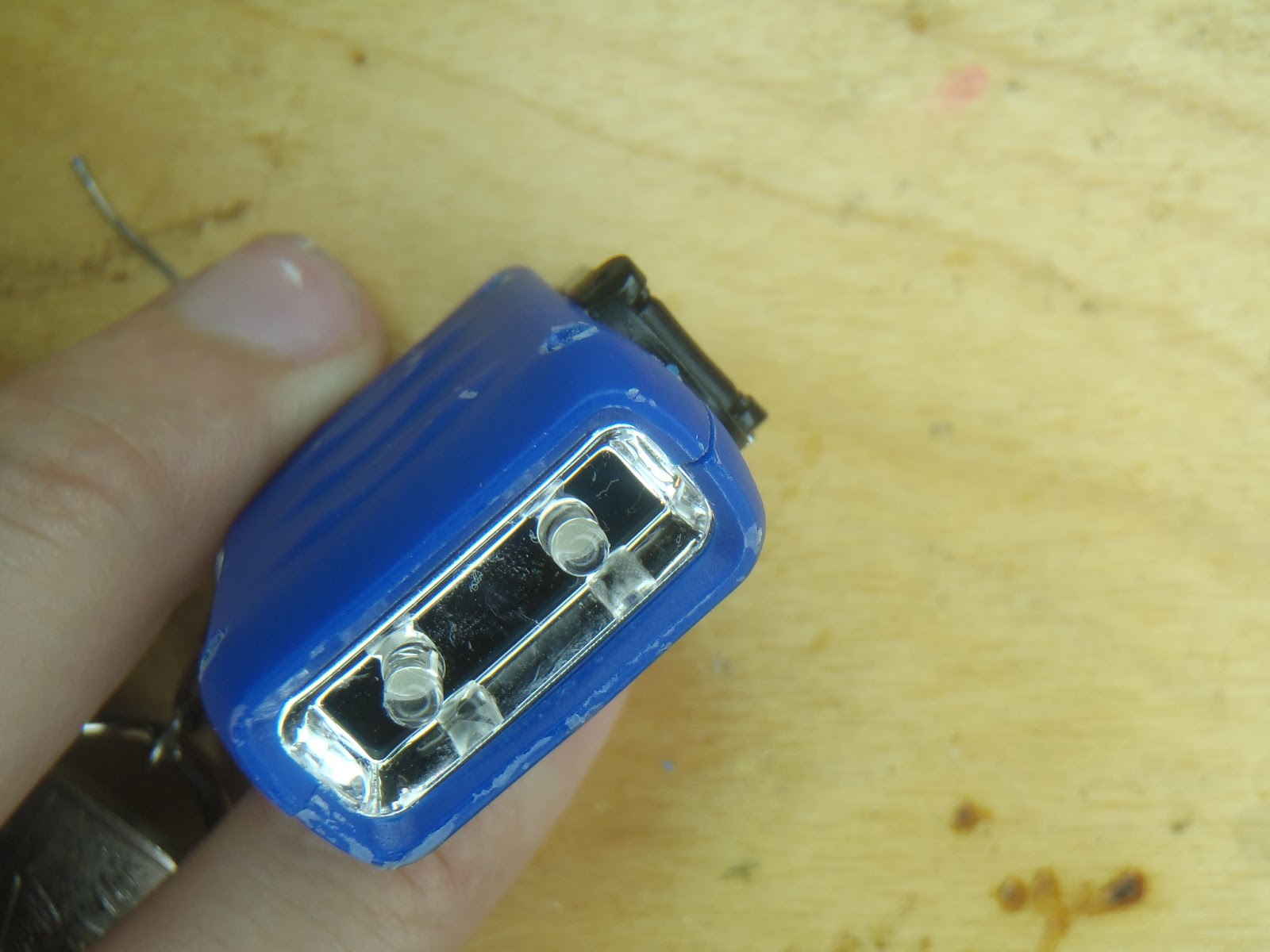
The external banana plugs are screwed and hot glued to provide extra support.

The button board is hot glued in so it is removable with a little heat. There is no easy way to screw it in so hot glue was the best option. The wire connector is hot glued on both sides to provide strain relief.

Don't forget to document your work! This blog is one of my ways of keeping a build log. I have many projects I've done that I have to relearn how I did them if I ever want to fix them. Keeping a log like this will help you in that process.

All in all a great little device that does its job and is easily modifiable and repairable by anyone, not just the designer.

Please leave any feedback on what I did wrong or what you would have done better :)

Also if you enjoy my posts please click the follow button on the top right.


Sunday, June 16, 2013

Adding Capacity


I was recently given a wind up light key fob but unfortunately the internal battery was no longer accepting a charge so constant winding was required. I was unable to turn it at a constant RPM so an unacceptable strobe light effect was produced. I really liked the little light so I decided to crack it open and fix it.


Most little charge up lights I've seen, whether they are solar powered or crank style, don't have a rechargeable battery and simply use a primary cell. Four very small screws later I discovered that is the case here too.


I could have swapped the little lithium coin cell out for a new one and had a working light again but I really liked that the wind up part of this key fob was real. I wanted some way to give it the ability to be wound up for a few turns and hold power for several seconds. I also didn't want to spend any money so it had to be from my parts bin. Luckily I work on a project a while back where I needed some very small ultra-capacitors. I had two 0.47F 2.7V capacitors left over that fit my requirements perfectly.


Looking at the PCB I could see the a full wave diode bridge rectifier, yes 4 whole diodes! They spared no expense. They fed into the non rechargeable battery, then the switch made or broke connection to the two LEDs.

It was simply a matter of de-soldering the battery and replacing it with the two ultra-capacitors. I chose to put the two in series so a higher voltage was capable and thus a longer run time. I could have added a joule thief and only one cap but that would have been a lot to cram in there.


Before I soldered the caps in place I first checked to see if they would fit. The answer is no, they would not fit without removing the board and having everything free floating. I didn't want to do that and I have also been trying not to make my projects look like the Borg made it. Cutting a piece of the case away for the caps to hang out of was a no go as well. I decided to try heating the plastic and adding a depression for them to fit into. This wound't look too ugly and should be easy enough to do.


With the caps fitting it was time to screw everything back together and see if it works. Success! About 10-15 fast turns (the faster you turn it the more power is produced) would get about 10 seconds of light. You could also tell when it was fully charged b/c it would start to spin very easily when cranked.

Tuesday, March 12, 2013

Larger Boards in EagleCad Free

A few years ago I made a large flexible LED sign on some copper clad kapton. I used the toner transfer method to etch the kapton but I quickly ran into the dilemma of board size. I was using the free version of eagle cad and was limited to 100mm x 80mm. My boards were in the range of 160mm x 120mm. After a little trial and error I found a way to bypass the board size limitation without modifying eagle cad in some illegal way.

First let me say this works best for a simple repetitive design. I needed it for the 1 layer surface mount display boards which used a simple layout repeated multiple times.

Starting in the board layout window draw a component. For me it is the large LED. I used the rectangle tool to draw the pads in the TOP layer and the line tool to draw the chip indications in the TPLACE layer.

Figure 1


Next I copied it around to form my 4 LED pixel.

Figure 2

This part is a little tricky. I laid down the traces without any nets for guidance. Use the line tool to mark where you want the copper to stay.

Figure 3

Repeat until the pixel block is complete. Copy pixel block to form half column block. Add connection pads to bottom and connect pixels.


Figure 4 : Rotated Left for better fit

Copy this around to form full display.

Figure 5

Success! Eagle cad will gladly let you make this board and export to PDF or gerber. Side note, each line you draw counts as a new net so DRC will still work.

Wednesday, September 28, 2011

Delay in postings

I am still working on this logic contest but my camera's broken.  I'm in the hardware testing phase so no post would be right w/o the pictures.  I will post more as soon as I get a new camera.

Friday, September 23, 2011

Test Test and Retest

In my last post I gloated about my DFF always starting in the LOW state... Turns out that is wrong.  I was testing to see if the 7400 can be used as a tri-state buffer and noticed that once in a while the DFF would start high.  This does not happen often, maybe 1 in 10 times, which it turns out is infrequent enough for me not to see it when I was first testing it.  I should have tested the circuit more thoroughly but I was too excited to fully evaluate it.  This mistake wouldn't have killed the entire design as there is only one part that absolutely needs to start low, but It could have added a nuance to the game where the car wouldn't show up sometimes and you have to toggle the power switch.

I added a simple fix that seems to work, I need to do further testing to ensure it does but I can't until the rest of the parts come in next week.  I added a capacitor and a resistor that makes the clock start high and go low when the capacitor drains.  This makes the initial state of D the start condition for the output.

The standard DFF using a single 7400 Quad NAND


The advanced implementation of the DFF

Tuesday, September 20, 2011

A Little Bit of Bread-Boarding

I finished the simulation a while back but have been busy so no new posts recently.  I am still trying to find the best way to upload the logisim schematic, any suggestions in that area would be appreciated. Here is the Logisim source file!

Screen Shot of Working Simulation

I noticed when I was working with logisim the D-flip-flops (DFF) I created using NAND gates always started out in an error state.  It took a full clock cycle for them to correct this then they functioned properly until the next reset.  I have a trigger using a DFF that must start low so I needed to build it to make sure it starts low.  Most of my NAND chips are on order but I did find one left over from a project I did a few years back.

Initial Power On DFF from NAND

As you can see from the picture the /Q line is active on power on.  The white wire is the D input and the brown wire is the Clock.  After clocking in a HIGH:

DFF from NAND HIGH state

It works!  I always get excited when I see LEDs light up when they are supposed to light up.  This proved that the DFF does start in the LOW state and does work.

I have started working on the LED matrix, specifically on how to defuse the LEDs and make them into nice looking squares... but more on that in the next post.


Tuesday, September 6, 2011

Game Criteria

I should have posted about this earlier but I wanted to get a feel for what I could actually accomplish before I came up with some grandiose planes.

With any project you need to have a plan of what you want to accomplish.  Even if you don't list out this plan or write it down you still have some kind of plan in your head.  I feel it is best to list out what is needed and then list how to accomplish it.  By doing this I can see holes in my design better then if I just keep everything in my head.

What the game needs:
1.A matrix of LEDs that displayed the level
2.The ability for the level to scroll
3.The top row of the level changes to make the road move
4.LEDs to represent the car
5.The ability for the car to move left and right
6.Collision detection between the car and the grass that would end the game
7.The game needs to get harder the longer it is played

How to accomplish these things:
1. A matrix of LEDs (duh) and memory in the form of D-flip flops to hold them.
2. Arrange the D-flip flops in the form of an 8 bit wide shift register.  This allows the screen to cascade down.
3. Put a new byte in the shift register every cycle.  Either random or from non volatile memory.
4. LEDs and D-flip flops again.
5. This is harder.  A shift register that allows for left and right shifting as well as a loop back on either end so the car would not vanish off the screen but would simply stop.
6. A lot of or statements that could cancel out the oscillatory thus ending the game.
7. At specific times the game will speed up by reducing the amount the oscillator is divided.

This list will change as the project goes on and the list of how to accomplish goals will become better defined.
I will re-post this list as the project progresses and things change.

Preview of bi-directional shift register: